Remote Field Testing

internal-rotary-inspection-system-iris
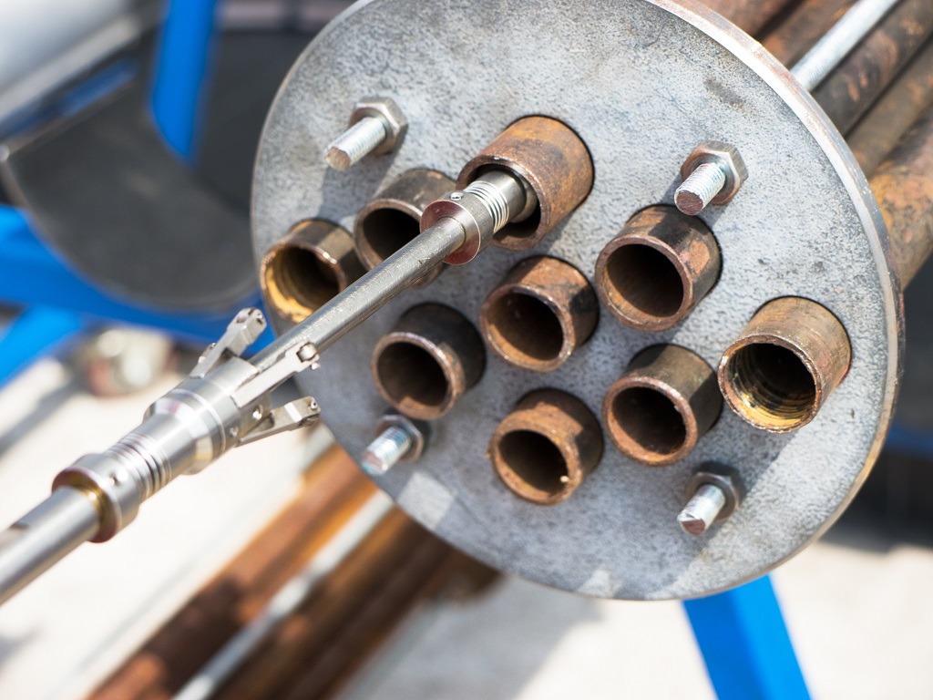
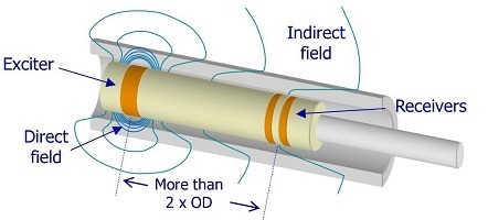
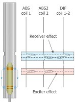
The Remote Field Technique is generally used to evaluate the condition of ferromagnetic tubes such as those found in process heat exchangers, boilers, and feedwater heaters. The most common material examined being carbon steel. The Remote Field Technique (RFT) should not be confused with other electromagnetic techniques such as eddy current, used to examine nonferrous materials. The RFT may be utilized to examine nickel, ferritic stainless and other tubing made of ferritic materials. Unlike eddy current, the RFT operates at lower frequencies, in the 50 to 500 Hz range for carbon steel. For inspection, an RFT probe, which has an exciter coil and two or more detector coils, is inserted into the tube. An A.C. magnetic field generated at the exciter coil transits out through the tube wall travels along the tube and passes back through the tube wall at a distance of more than two tube diameters. The tube wall thickness is directly related to the travel time or the phase of the A.C. magnetic field. Therefore, measurements of wall loss can be obtained using phase measurements.

Reference Codes and Standards

  • ASME Section V, Article 17
  • ASTM E-2096

General Concept

  • The basic probe is made with one exciter coil and two receiver coils.
  • Two main fields are present, coupling the energy between exciter and receivers:
  • The direct field is centered around the exciter coil and is rapidly attenuated relative to the distance down the tube.
  • The indirect field is diffused outward through the tube wall, propogates along the tube axis, and is then rediffused back through the tube wall.
  • The zone in which indirect field is dominant is called the remote field zone. This zone is present at a distance greater than two tube diameters.
Remote Field Testing

Characteristics of RFT Technique

  • Suitable for ferromagnetic pipes and tubes such as those found in boilers and heat exchangers.
  • Same sensitivity is achieved for internal and external flaws.
  • Technique is relatively insensitive to probe lift-off or wobble.
  • Can be used to examine thick tube wall.
  • A lower fill factor enables the inspection of partially scaled tubes and boiler tubes with swages and bends.
  • Centralization of the probe is not as critical as it is for ECT inspections.
    Typical pulling speed is between 0.10 m/s and 0.3 m/s.
  • RFT technique cannot differentiate between ID or OD defects, the coils only measure the total thickness of the material.

Typical Defect Response

When the probe moves past a defect in the tube, the response is seen in terms of two effects:

Receiver effect

  • The first receiver produces a signal when it moves past the defect, and it is followed shortly after by a similar signal from the second receiver coil.
  • The subtraction of both receiver signals generates the “S” shaped differential signal.

Exciter effect

  • The exciter coil moves past the defect, affecting the field sensed by the receivers.
  • Both receiver coils sense the exciter effect at the same time and produce almost identical signals.
  • If the defect is large, the exciter can have a small effect on the differential signal because both receiver coils have a slightly different response.
Remote Field Testing

Please fill details to download the brochure